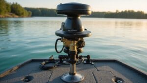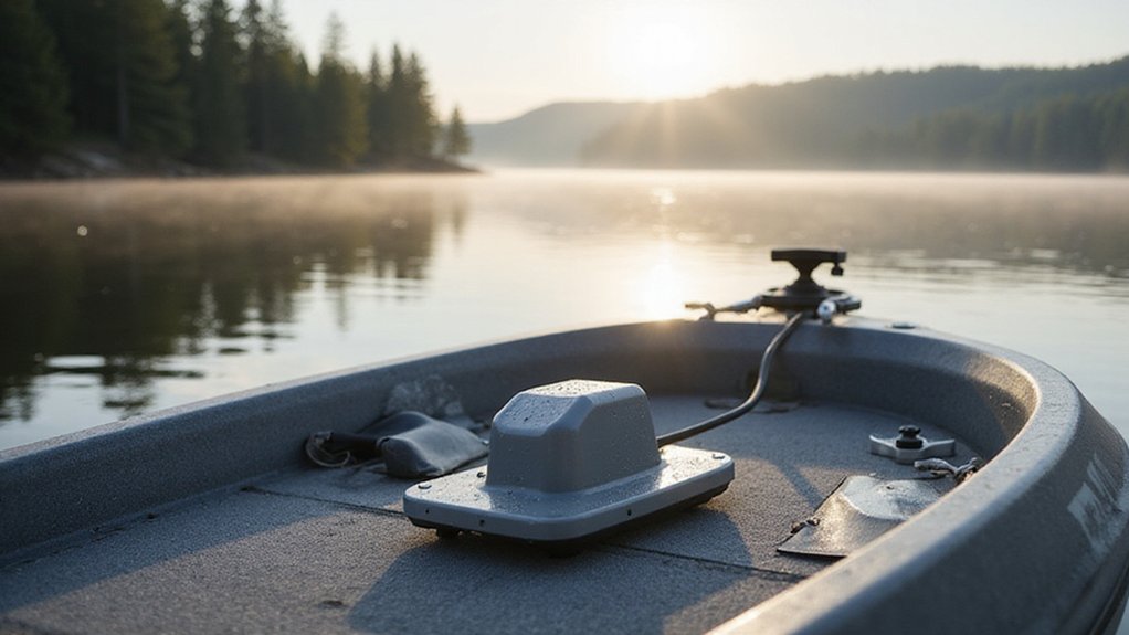
Struggling to find the best way to mount your LiveScope transducer on a trolling motor? Getting it right is key to achieving clear, crisp images of what’s beneath the surface.
By choosing the right mounting bracket and ensuring the transducer is positioned at a true 0-degree angle, you can optimize your imaging.
Proper cable routing with enough slack also helps prevent damage over time.
Keep reading for step-by-step tips to get your transducer set up perfectly.
Pick the Right LiveScope Mount for Your Model (LVS34, LVS42HD, LVS44)
Choosing the right LiveScope mount depends on your specific model—LVS34, LVS42HD, or LVS44—and the hardware it comes with. The LVS34 primarily offers two mounting options: shaft mounting for forward and down views or a barrel mount. It does not support perspective mode. The LVS42HD and LVS44 include a wider range of mounting options, such as a 0° shaft mount, a barrel mount, and an adjustable perspective mount, giving you more versatility. Always verify compatibility with your trolling motor’s shaft diameter and shape. Check aftermarket specifications for your motor model because some brands or types may not be compatible. For those seeking broader performance insights, reviewing a top speedometer can help complement your boat’s electronics. New anglers should also consider that simpler fish finders often have easier mounting setups and clearer display menus. Prioritize installation safety by ensuring clearances and avoiding forcing hardware that doesn’t fit. Proper matching prevents hardware damage and ensures reliable operation on the water. During installation, you must cut a segment off the transducer’s plastic piece to fit the shaft. For reliable communication while on the water, pairing your setup with a remote marine radio ensures you can stay connected from anywhere on the boat.

Complete Kit for Easy Installation: Our no drill transducer mount kit includes all necessary accessories for a seamless installation: 1 transducer pad block, 1 scouring pad, 1 cleaning wipe, and 3 black cable clips; Simply clean the installation surface, peel off the adhesive, align the position, and press firmly for a few minutes; (Note: Please wait 18 hours before mounting the transducer to ensure the adhesive sets firmly, reducing the risk of detachment during use
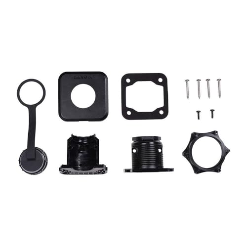
Flush-mount design

🛥️[Product Overview] Stern Pad, Screwless Transducer Mounting Plate kit, Marine-Grade Transducer Mounting Board Hardware Kit.
Align the Bracket With Arrows up and the Groove Forward
Start by orienting the mounting bracket on the trolling motor shaft so that the arrow on the front half points upward. The arrow is your primary visual cue for correct alignment. Make sure the arrow is facing straight up, not sideways or downward, and avoid flipping or rotating the bracket before tightening any fasteners. If the shaft diameter is less than 25 mm or 1″, use the rubber lining to ensure a proper fit. Be aware that a misaligned bracket here can cause similar accuracy problems to a faulty fuel sending unit in a boat’s fuel system. For optimal performance, this precise alignment is as critical as selecting a quality fish finder for accurate underwater readings. You can confirm the bracket is level by checking that the motor does not flicker or fluctuate in speed, which would indicate a pressure or alignment issue.
Next, focus on aligning the groove. The notch in the bracket must seat cleanly into the shaft’s groove. Check that the bracket sits flush against the shaft without forcing it—if the notch doesn’t match, re-position until it does. The center screw hole should face the front of the trolling motor, aligning with its forward direction. Ensure the bracket remains square to the shaft throughout this step. Proper orientation and groove alignment now prevent issues during operation. Confirm everything is correctly positioned before you tighten the screws.
Secure the Transducer at a True 0° Angle for Cleanest Imaging
Securing the transducer at a true 0° angle is essential for the clearest imaging. To do this, use a zero-degree clamp instead of the factory angled bracket. This correction aligns the transducer directly ahead or downward, matching the sonar beam with your motor’s orientation and providing an accurate view of your lure’s position. A DIY solution using two pieces of 1-inch PVC pipe and a metric screw can achieve this zero-degree mount for under ten dollars. Keep the transducer level with the trolling motor shaft, avoiding tilting, so that the sonar returns are consistent and easy to interpret. For accurate positioning, pay attention to screen readouts that indicate the beam angle and depth range. For the best performance, you should also consider top depth finders that support this precise mounting method. When selecting your transducer mount, ensure it is compatible with your boat model to guarantee a secure fit and optimal sonar performance.
Apply a waterproof coating to all exposed hardware to prevent corrosion, which can cause misalignment and degrade image quality. The clamp’s vibration damping features help prevent shifting when the motor moves, maintaining a steady and accurate image. Tighten all hardware securely but leave some room for controlled adjustment during installation. Mount the transducer no more than two inches above the motor foot to avoid interference or cavitation. Once installed, set your viewing mode after confirming the transducer’s position for optimal performance. A true 0° mount keeps your sonar returns clean, making your display more intuitive and reliable.
Route the Transducer Cable With Slack to Avoid Pinch Points
Routing the transducer cable with adequate slack prevents damage and ensures reliable sonar performance. Leave at least 10 centimeters of slack above and below each rotating joint to create a service loop that allows full transducer rotation in both directions. This extra length prevents tension buildup during steering, which can stress the connection and affect accuracy. Use black electrical tape to secure the cable to the shaft, anchoring it above and below pivot points to provide strain relief and reduce movement. To maximize visibility and safety in low-light conditions while on the water, consider how a top anchor light complements your overall boat electronics setup. Avoid tight zip ties, as they can crush the cable and cause damage. Run the cable through the starboard side of the mount to prevent pinch points during stow and deployment. Before tightening everything, test the transducer’s full range of motion to confirm the cable clears all moving hardware with no tension at any angle. Keep the cable away from the propeller and other electrical wires to avoid abrasion, interference, and potential damage. For optimal setup, ensure your system includes a reliable unit that compares well on saltwater performance and value with other top picks. The Garmin Echomap Ultra 2 126SV provides exceptional clarity for this cable routing configuration. Support the cable with a rod sock inside the boat structure for additional protection and organization.
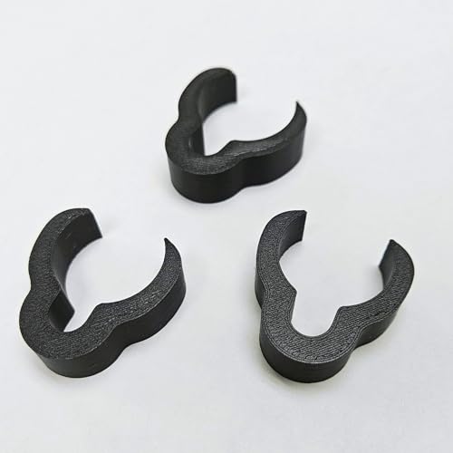
Perfect Fit – Designed to fit 1 1/8” and 1 1/4” transducer poles Secure Hold – Clips snap firmly in place and will not slip off freely 3 Pack Value – Includes three clips for complete cable organization Cable Protection – Prevents tangles and keeps cables safe from snags Made for Anglers – Streamlined design tested for real fishing conditions
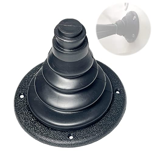
Marine grade cable boot provides a fully open area, can organizes and protects engine control cables, wires, or fuel lines and improve the looks of any rigging job.
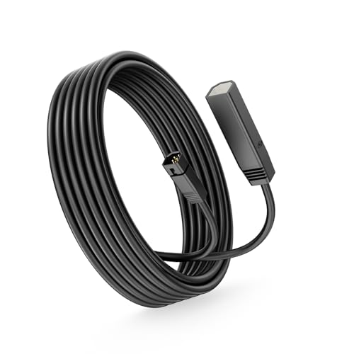
Wide Humminbird Compatibility:Compatible with Humminbird transducers for HELIX 5/7/8/9/10/12/15, PiranhaMAX, and Series 800/600/700/1100/500/90 fish finder setups.
Match Your Mount to Your Fishing Style: Forward Scan, Down, or Perspective
To match your mount to your fishing style, start by routing your cable with enough slack. For forward scan, rotate the bracket into a side-shaft position so the transducer faces ahead. This angle allows you to scan around cover and structures while moving slowly. For a down view, rotate the arm perpendicular to the shaft and align the single indicator ridge with the bracket’s center mark. This setup ensures you see directly below the boat. Perspective mode requires positioning the arm parallel to the shaft and lining up the double indicator ridges. With this, you get a wider, top-down view of what’s ahead. These mounting methods let you switch viewing angles easily by loosening the adjustment knob—no tools needed. The same shaft mount works for all three modes, so you can adapt quickly while on the water. Always ensure sufficient slack in the cable for strain relief to prevent damage during motor movement.

✅Fits for Garmin Panoptix LiveScope LVS12 Transducer. Fit for EchoMap Ultra 102sv, 106sv, 122sv, 126sv; GPSMAP 8410xsv, 8412xsv, 8416xsv, 8610xsv, 8612xsv, 8616xsv; Striker 7SV, Striker 9SV; Fishfinder 220, Fishfinder 400. Directly replace for part number 010-12846-02.It improve the transducer running performance and genuinely supports the sensor without letting go of any fish.

✅【Essential Fishing Device】: As an important component, our mounting bracket allows you to freely arrange the position of the fish finder sensor, which is an indispensable fishing device.

【Enjoy Fishing Life Better】 Frustrated because the picture on your electronics wasn’t the same as advertised? 7400931 MHX XNT Transducer Bracket is a nice addition for your boat that helps your skimmer transom mount transducer to find fish easier to find and get the right scan image. Efficiently improve your transducer running performance without letting go of any fish!
Don’t Make These Installation Mistakes: Wrong Angle, Tight Cable, Misaligned Bracket
To avoid installation issues, leave sufficient slack on the cable near the transducer for strain relief. On rotating shafts, ensure at least 4 inches of extra cable above and below the joint, with a total length of about 10 inches, to prevent chafing and damage. Use only electrical tape for securing the cable; zip ties can harm the insulation or cause unnecessary stress. During deployment or steering, route the cable away from the propeller to avoid interference or accidental damage. The bracket’s 8-degree offset also helps keep the beam clear of the motor housing, further reducing the risk of cable contact during rotation. For a stable installation, selecting a high-quality bracket ensures the transducer remains secure during extended use. Understanding how a thru-hull transducer works can help boat owners appreciate the importance of proper beam alignment for accurate readings.
When attaching the bracket, align it so that the arrow points upward and the center hole faces forward. Proper alignment prevents twisting of the transducer body, which could distort beam direction and reduce measurement repeatability. Also, verify that the transducer and bracket do not interfere with the motor stowing or shaft movement, ensuring smooth operation without obstructions. Securing the clamp snugly with an Allen wrench, while leaving the rubber washers free to pivot, maintains the needed adjustability for final on-water fine-tuning.

🏆【OPTIMAL VIEW】This 0 degree pole mount holds the Panoptix LiveScope LVS32 transducer, ensuring you get the best possible view while ice fishing and open water fishing. Whether you're looking for hidden fish or precisely tracking a school, this rod holder will help you do it all.

Enjoy Your Fishing Life - How long has it been since you went to explore the outdoors trip with your family and friends? Do you enjoy outdoor fishing life? Our Transducer Mounting Bracket can help your transom mount transducer to find fish easier and identify the accurate and clear scan images easier. Get our transducer mount for easy winning in fishing tournaments with friends.

Professional:The transducer mounting plate is specially designed for XNT transducer, Compatible models XNT 9 20, XNT 9 20 T, XNT 9 QB 90 T, XNT 9 QB 90, XNT 9 SI 180 T
Troubleshoot Your Transducer Angle for Clearer Views
Start by selecting the appropriate viewing mode—Forward, Down, or Perspective—before fine-tuning your transducer angle. Use your trolling motor barrel as a level reference; aligning the transducer with it helps reduce tilt-related distortion. If the image sways or targets look off-center, the transducer’s angle is probably incorrect. Check your Depth calibration to ensure the beam aligns properly with your chosen view. For minor discrepancies, adjust the Pitch Angle setting or enable Auto Stabilize. Be cautious of signal interference from nearby electronics; if swaying persists, consider relocating your mounting position. After changing modes or rotating your motor, always retest against a fixed target to confirm optimal image clarity. Small adjustments to the transducer angle can greatly improve clarity and sharpness of your sonar images. For bank fishing, comparing top fish finder options can guide you in selecting a model that pairs well with your mounting setup. When mounting on the starboard side, ensure the transducer angled back matches the mount’s orientation for accurate forward reading. To confirm the transducer’s signal is not failing, you should test it the same way you would test a boat tachometer to check for electrical continuity and stable power supply. Understanding how to interpret the screen readouts on your Humminbird Helix 5 will help you verify that the sonar return matches the adjusted transducer angle.

Motor-Mounted Sonar: Allows mounting of transducer on lower unit of most Minn Kota bow- or transom-mount trolling motors

Universal Compatibility: 1840201 410150-1 MKR-15 mounting kit is designed for Minn Kota lower unit trolling motors with shaft diameters of 3-1/4", 3-5/8", 4", and 4-1/2"

Applicable: This transducer mounting bracket is designed for Lowrance Active Imaging 3-in-1 transducers and Minn Kota trolling motors, perfect for all Minn Kota trolling motors with built-in US2 transducers