If your boat’s tachometer isn’t showing the right readings, it can be frustrating. You need to know if it’s sending correct signals or if it’s time for a fix.
By testing the power supply, signal wire, and comparing it to a reference, you can pinpoint the issue.
Below, I’ll walk you through each step to help you get your gauge working accurately.
Check Power: Test for Voltage at the Tachometer
To test for voltage at the tachometer, start by turning the ignition to ON with the engine off. Use a multimeter set to DC volts to measure the voltage between the tachometer’s power terminal and a known good ground. A healthy circuit should read close to the vehicle’s battery voltage, typically between 12 and 14 volts on a 12-volt system. If you see a zero reading, it indicates a power-feed issue. Next, disconnect the electrical harness from the rear of the tachometer and probe the battery pin with your multimeter. Confirm that it shows the same voltage as your battery voltage. If it doesn’t, inspect the harness and wiring for breaks, corrosion, or loose connections. Comparing the voltage at the harness to the battery voltage can reveal a voltage drop, which points to resistance in fuses, connectors, or wiring. A properly functioning circuit should deliver nearly full system voltage directly to the gauge, so accurate voltage checks are essential before proceeding with further diagnostics. For boaters with sensitive electronics, a top radar mount ensures stable readings by reducing vibration interference. Some boaters also rely on fish finders to monitor electrical systems while on the water. When checking the horn circuit, ensure that the horn button connections are also clean and free of corrosion for reliable operation.

【Meet Different Needs】 The 12V round voltmeter comes with a panel and a nylon nut, which can be mounted separately on the 29mm diameter mounting hole or fixed on the matching panel, so that it could meet your different mounting needs.

【Function】7 Solid Color Settings will meet your requirement. The button on the back can switch color of light you want-Colors Include Blue, Red, Green, Teal, Purple, White & Yellow

small engine tachometer :The digital tachometer can accurately measure the rotational speed of all strokes (cylinders 1-8),including 2-stroke or 4-stroke gasoline engines, RPM Range of 10-15000 rpm,Accuracy with 1%,which enhance the engines safety and reliability
Trace the Signal Wire and Verify the Source
Start by finding the gray tachometer signal wire that runs from your gauge back to the engine. Follow its entire wiring route through harnesses, connectors, and control boxes to ensure it is intact and properly routed. Confirm that this wire connects to the correct signal source—avoid random conductors or incorrect terminals. Check your engine’s documentation to identify the designated tach signal source, which could be an alternator terminal, a stator tap, or the coil negative terminal. On older outboards, it is often the ignition system; for modern engines, it may be the engine control unit (ECU). Ensure the wire is connected to the proper gauge terminal, typically labeled as the signal or sender post. Verify that the source produces frequency pulses rather than a steady direct current (DC). Use a multimeter or oscilloscope if available to observe these pulses. Steady DC signals indicate a false or incorrect source. This process helps isolate any wiring breaks, misroutes, or incorrect connections, confirming you are testing the proper signal path before proceeding to further diagnostics. A failing signal source may produce low oil pressure readings when tested, similar to the pressure loss symptoms described in the referenced guide. To rule out gauge malfunction, cross-check the reading against a known-good unit or consult marine gauge compatibility charts that list matching signal types and voltage ranges for your specific engine model. For a reliable baseline, consider consulting a review of the best speedometer for boat to ensure your signal source aligns with recommended gauge standards.
Compare Your Gauge to a Handheld Reference Tach
Begin by confirming that the signal path from the engine to the tachometer is intact and properly sourced. Next, use a handheld reference tach to compare readings at three steady RPM points: idle, midrange, and near cruising speed. Hold each engine speed steady until the readings stabilize. Record the difference between the boat’s dash gauge and the reference tach at each point.
Look for consistent offset patterns. If the dash gauge reads consistently higher or lower than the reference across all points, it indicates a calibration issue with the display. Larger discrepancies at higher RPM suggest the gauge may be interpreting the signal incorrectly or has a faulty sensor. Use the more accurate handheld tach as your benchmark. While this testing method ensures accurate engine data, you can improve your on-water electronics by selecting a Lowrance fish finder designed for clear display performance in harsh conditions. Apply the same principle of using a reference instrument to verify other onboard electronics like your VHF radio. Understanding the boat’s stern light color helps ensure you comply with navigation lighting regulations during nighttime operation.
Repeat the measurement at each RPM point to ensure repeatability. A small, uniform offset—within a few RPMs—can often be corrected through calibration. Significant or erratic variations point to a faulty gauge or an incorrect signal source. Conducting these comparisons helps identify whether the issue lies with the gauge itself or the input signal.
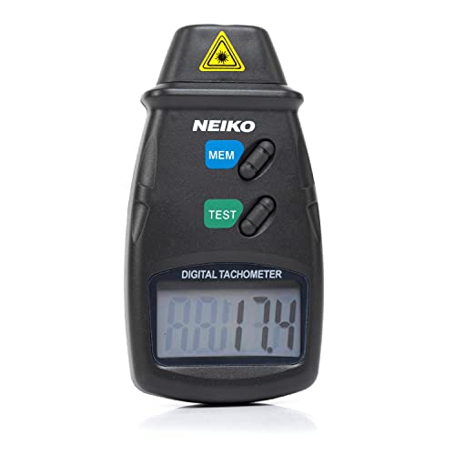
TACHOMETER VS. SPEEDOMETER: While a digital speedometer will read the current speed of a vehicle, this automotive tachometer is used for measuring the rpm of a revolving shaft, as with the driveshaft of an automobile.

❤ Timing range: 1 minute to 99999 (min MIN), 1% accuracy. used in the measurement of up to 8 cylinders (rotation speed RPM) of 2-stroke or 4-stroke fuel or gasoline engines, engine working timing accumulation time

Professional High Accuracy RPM Testing: Accurately measure rotational speed from 10 to 99,999 RPM with ±0.05% precision and fast response performance. Ideal for motor diagnostics, engine maintenance, machine inspection and equipment troubleshooting
Set the Boat Tachometer’s Calibration for Your Engine
To calibrate your Boat Tachometer, locate the adjustment pot behind the “ADJ” plug. Run your engine at a known RPM above 1000 to ensure accuracy. Using a small Allen key, slowly turn the adjustment pot until the gauge needle matches the actual RPM reading. For precise calibration, use a multimeter to measure the frequency from the stator coil and confirm the pole setting matches your outboard’s charge coil. Additionally, consider using a dedicated catfish finder for better sonar performance when fishing at depth. A CHIRP fish finder provides continuous frequency sweeps for superior target separation compared to traditional sonar. After setting the correct reading, replace the weather seal plug to protect the adjustment. Finally, verify the tachometer’s accuracy across your typical operating range to confirm the setting. Lock in your calibration to keep your readings consistent.

Reliable Quality - Made of high-quality materials, provide accurate degrees, stable quality, and long service life

【Function】7 Solid Color Settings will meet your requirement. The button on the back can switch color of light you want-Colors Include Blue, Red, Green, Teal, Purple, White & Yellow

Sierra 68412P Eclipse 4 Gauge Outboard Kit Includes: 68399P - Tachometer / Hourmeter, 68396P - Speedometer, 68390P - Fuel, 68408P - Voltmeter
Decide Between Replacement and Repair of a Faulty Tachometer
If the tachometer’s needle remains dead despite confirmed power and a clean signal, replacing the gauge is usually the best solution. A faulty internal circuit or a failed voltage regulator indicates the gauge has reached the end of its lifespan. These issues are not typically fixable with a simple wiring repair.
Address external wiring faults first, such as corroded terminals, loose ground connections, or a blown fuse, as these are easier and less costly to repair. If you notice the needle only moves when tapped or wobbles erratically, the internal movement mechanism is likely damaged, making replacement the more practical choice. When comparing your tachometer reading to fishfinder data, ensure you are using a high-quality humminbird fish finder for the most accurate RPM correlation.
Consider the cost difference: repairing or rebuilding an internal component can approach the price of a new gauge, whereas fixing external wiring is quick and inexpensive. For reliable engine monitoring, especially with RPM readings that impact engine health and safety, it’s better to replace a malfunctioning tachometer that cannot be trusted. You can verify engine speed against your Garmin Striker 4 to double-check tachometer accuracy before committing to a replacement. You can also compare the tachometer reading against bait ball returns on the fishfinder to confirm if the gauge is reporting correctly under load.