If your horn isn’t working, the relay might be the culprit. Testing it isn’t complicated and can quickly tell you if it’s faulty or if the problem lies elsewhere.
In this guide, you’ll learn simple steps to check your horn relay, including how to inspect, test, and swap it if needed.
This will ensure you’re on the right track to get your horn working again.
Where to Find Your Horn Relay Under the Hood
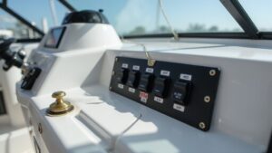
Your horn relay is typically located in the main fuse box under the hood. This fuse box is usually positioned near the battery and covers by a black plastic lid. Remove this lid to access the fuse box diagram printed on its underside, which clearly labels the relays. Look for a label such as “HORN” or “HORN RELAY.” If the relay isn’t immediately obvious, consult your vehicle’s owner’s manual for the exact location. Vehicle layouts differ significantly, so relying on the diagram rather than guessing is essential. Focus on the “R” number codes on the diagram to help identify the horn relay. If you don’t find it under the hood, it could be located inside the vehicle, under the dashboard or kick panel. Always start by checking the fuse box diagram to avoid unnecessary searching. For boaters, checking the quality and performance of your electrical components is just as important as ensuring your horn relay works. Consider organizing your boat’s wiring with a dedicated switch panel to prevent similar electrical confusion. Just as a chartplotter uses GPS satellites to plot your precise position on the water, understanding your vehicle’s electrical system requires accurate reference points like the fuse box diagram. To verify the relay’s function once located, use a 12V power source to energize it and listen for a click that confirms operation, checking continuity with a multimeter for a definitive test.
Check the Relay for Cracks, Burns, or Corrosion
Visual inspection of the relay for cracks, burns, or corrosion is crucial before testing. Look closely at the casing, terminals, and socket for any visible damage. Cracks, burns, or scorch marks indicate overheating or electrical faults that can cause circuit failure. Check the mounting for deformation, melted plastic, or scorch marks, as these signs point to overcurrent conditions. Corrosion on the pins or inside the socket disrupts circuit continuity and can mimic relay failure. Use a flashlight to identify fine damage on terminals and contacts, such as pitting or discoloration from arcing. Any burn marks, cracks, or rust should be treated as potential failure risks. Clean corroded parts carefully, or replace the relay if the damage is severe. A damaged housing or corroded socket can directly break circuit continuity, so addressing these issues is essential before moving on with testing. On a boat, similar visual checks should be performed on all electrical components, including the night vision camera housing and connectors. For a reliable setup, consider that a speedometer for boat must also maintain clean connections to prevent similar electrical faults. Investing in a stable mounting system, such as one used for marine electronics, helps reduce vibration that can loosen terminals over time.
Test a Horn Relay’s Coil Resistance With a Multimeter
Check the coil resistance of your relay by de-energizing it completely. Confirm your multimeter is correctly calibrated by touching the probes together; you should see a reading close to zero ohms. Set your multimeter to resistance mode, using a low range such as 200 ohms for accurate measurement. Locate the coil terminals, usually pins 85 and 86. Place the probes firmly across these two terminals only, ensuring good contact. A faulty relay can be identified by a shorted internal coil resulting in near zero resistance. A healthy 12-volt relay coil typically reads between 50 and 120 ohms. If you see an open circuit, indicated by OL, or a reading near zero ohms, indicating a short, the relay needs replacing. Ensure the probes are clean and contact is direct to avoid false readings. Remember, this test assesses the electrical integrity of the coil, not the relay’s switching ability. A reliable anchor or horn relay should offer consistent resistance for your marine electrical system. For boats exposed to vibration and moisture, selecting a relay with a robust sealed housing ensures the coil reading stays stable over time. When choosing a relay for your vessel, consider features like a weatherproof design that protects against salt spray and corrosion.

【24V 40/30A PEAK CAPACITY】Rated for 24V DC commercial systems with a 40A max peak switching current for Normally Open (NO) and 30A for Normally Closed (NC) contacts. Always keep continuous loads 10% to 15% below rated values for optimal electrical safety

Integrated Diode: Each relay includes a built-in diode that suppresses induced voltage during switching, safeguarding your electrical components from potential damage.

【IP65 Waterproof】The shell of 5-pin relay harness kit is made of the durable insulation material, the 5 terminals are sealed with strong cap and the rubber ring, making it connected tightly for better waterproof and dustproof so it can work in any harsh environments.
Energize the Horn Relay and Listen for a Click
To confirm the relay’s mechanical operation, energize its coil by connecting battery positive to terminal 86 and battery negative to terminal 85 with fused jumper leads. Keep the relay isolated from the vehicle circuit to avoid interference. When voltage hits the coil, you should hear a sharp, clear click—that’s the internal switch slamming shut. This sound indicates the relay is functioning mechanically as intended. You can also lightly touch the relay body; you’ll feel a matching vibration with each click. A weak, delayed, or absent click suggests the coil is dead or the armature is sticking. Cycle power several times, ensuring each energizing event produces the same crisp click. Inconsistent clicking means the relay might be marginal and unreliable. If you get a clean click every time, the coil and mechanical actuation are likely fine. No click after multiple tests means you should replace the relay or double-check your supply connections before probing load-side wiring. For comparison, a marine sound bar requires a similar level of reliable electrical connection to deliver consistent audio performance in harsh environments. Just as a pitot tube relies on precise fluid pressure to provide accurate speed readings for a boat, a horn relay depends on steady voltage to ensure consistent mechanical switching. Marine speakers, by contrast, often feature waterproof construction to withstand constant exposure to moisture and spray.

Interchangeable/Compatible with all automobiles and devices equipped with 12V DC power source
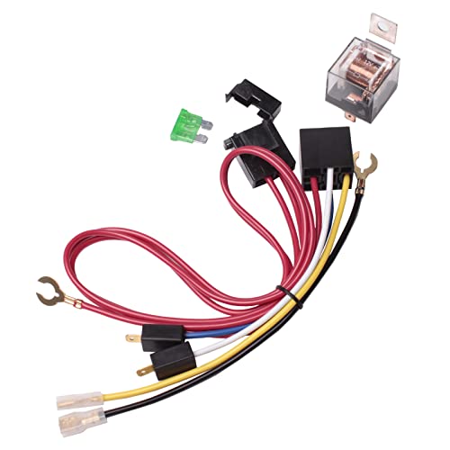
Interchangeable/Compatible with all automobiles and devices equipped with 12Volt DC power source

Practical Function: This double-horn wiring harness relay kit is designed to ensure the proper functioning of vehicle horns by enabling low-current switches to control high-current horns. This product is guaranteed to deliver clarity and consistency in the sound of the double horns
Verify the Switched Terminals Have Power Output
Verify that the switched terminals have power output, start by checking terminal 30 with a multimeter set to DC volts. It should read a steady 12 volts, indicating a proper power supply. If there’s no reading here, the issue lies upstream, possibly with the source connection or fuse.
Next, energize the relay to activate the switch. Then, test terminal 87 with your multimeter. When the relay is powered, terminal 87 should show battery voltage; if it remains at zero or below expectations, the relay contact inside may be faulty and failing to close. Understanding how the relay’s switching mechanism operates can help you pinpoint this failure, especially in a marine environment where corrosion is common. For a more thorough test, check continuity between terminals 30 and 87 while the relay is energized. You should only get continuity when the relay is active. A lack of continuity indicates burned or worn contacts. Be sure to identify the correct terminals before testing to avoid false results. Consistent voltage at terminal 30 but no power at terminal 87 when energized suggests a contact or relay malfunction, and this type of horn relay failure is often triggered by excessive moisture or salt spray. Using a Power Probe Basic, you can supply power to terminal 5 to rule out wiring and horn ground issues, as demonstrated in the horn circuit diagnosis. For a clean installation, ensure all connections are soldered and sealed to prevent corrosion from salt spray. When testing in harsh conditions, consider how corrosion resistance in marine electronics like Lowrance fish finders can inform your approach to protecting relay terminals.
Swap the Relay With an Identical One (Fastest Test)
If an identical relay is available nearby, swapping it with the suspected horn relay is one of the fastest tests you can perform. Begin by matching the part number, terminal layout, and size to ensure you don’t damage your circuit during troubleshooting. Turn your vehicle off, then pull the horn relay straight out. Insert a known-good relay from a non-critical circuit, such as the A/C system, into the horn socket. Activate the horn to see if it works. If the horn sounds after the swap, it confirms a relay failure. If there’s no change, the problem likely lies elsewhere in the circuit. Relays are critical components for vehicle electrical systems, so always verify they share the same part number before swapping. Similar to how a Garmin transducer mount provides a secure and reliable connection for your trolling motor electronics, a proper relay swap ensures a stable test environment. This method also benefits from using clean, reliable wiring to prevent intermittent faults during testing. To ensure your test is accurate, remember that a faulty fuel tank sending unit can also cause intermittent electrical issues similar to a bad relay. To double-check, swap the relays back to their original positions. If the horn only works after swapping, then the faulty relay was the cause. This method doesn’t require a multimeter and quickly rules out a relay issue from other potential faults. If necessary, replace the suspect relay with a new one to ensure reliable operation.

Highefficiency current transfer: a clear and loud horn sound, enhancing driving safety by providing a alert mechanism

Direct Fit Replacement: Designed to replace OE part numbers HR159T and 25630-79960 for seamless installation.

Direct Replacement: Replaces part number 25630-79960 to restore proper horn function in compatible vehicles.
What If the Relay Tests Good but the Horn Still Won’t Work?
Even if the relay tests good but the horn remains silent, several other faults could be at play. Begin by inspecting the fuse, which can blow or develop corrosion at the terminals, cutting off power. Use a test light rather than relying solely on visual inspection to check for power at the fuse and related circuits. Next, test the horn directly by applying battery power; if it doesn’t sound, the horn itself is likely dead. It’s common to find missing power or ground at the horn connector, so verify both sides for continuity. Wiring near the front end can also be damaged—especially around the grille—so check those wires for breaks or corrosion. If power and ground are present, the issue might be the horn switch circuit. A faulty spiral cable or button won’t trigger the relay, and pressing the horn may not produce the relay click. Finally, examine the connector fit and look for corrosion or loose contacts in the trigger path to ensure proper signal flow. Remember that relay testing should include checking for internal contact issues if the relay clicks but fails to activate the circuit. For those who also fish from kayaks, similar troubleshooting principles apply when checking the mounting bracket stability for electronic components. To avoid false readings, always confirm the test light is functioning on a known power source before relying on its results, which parallels verifying transducer performance during sonar setup.

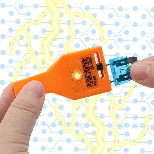
Nerites Fuse Tester – Ideal for One-Time Fuses The Nerites fuse tester is perfect for checking disposable fuses. It allows quick and easy removal and helps inspect whether a fuse is blown, making it an essential tool for removing and testing fuse arrays.
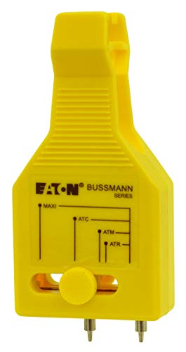
QUICKLY TEST BLADE-STYLE AUTOMOTIVE FUSES – Bussmann FT-3 Fuse Tester helps diagnose blown or functioning blade fuses in seconds, making it easy to identify electrical issues in cars, trucks, SUVs, RVs, boats, and other 12V automotive applications.