Are you trying to wire a fuel sending unit but unsure where to start? Getting it right is key to accurate fuel readings, and it’s simpler than it seems.
By the end, you’ll know how to connect the wires correctly, ensure proper grounding, and test the setup so your gauge works smoothly.
Keep reading for the full step-by-step guide.
Identify Your Fuel Sender Terminals and Wire Functions
Identify your fuel sender terminals by their markings: look for “S” for the signal wire connected to your gauge, and a “-” or ground symbol for the ground connection. If you see a “W,” that indicates a warning-light output. Always double-check your OEM wiring diagram to ensure correct matching of terminals; mismatching can cause inaccurate fuel readings. Understanding how a chartplotter works in practice can help integrate your fuel data with navigation displays for better trip planning. For reliable nighttime operation, consider a navigation light upgrade that meets USCG visibility requirements for jon boats.
Next, verify your fuel sender’s functionality through resistance testing. Use a multimeter to measure resistance between the signal and ground terminals while moving the float. A typical resistance range is 240 ohms when the tank is empty and 30 ohms when full. The resistance should change smoothly as the float moves; any infinite or zero ohm reading indicates a faulty sender. Performing this check upfront helps prevent troubleshooting issues later and ensures accurate readings from the start. Understanding how your marine radio communicates with other onboard systems can also improve installation reliability.

【Excellent Fit】: This fuel sender gasket kit complete with fine / course replacement screws and washers. Our fuel tank sender gasket has 5 holes for electric and mechanical fuel sending units

[High Precision and Long Life]: The exterior is made of stainless steel, and the interior is controlled by high-quality reed switches. The sensor is corrosion-resistant, does not rust, has a long life, stable output signal, and accurate measurement. Suitable for gasoline, diesel, water, methanol, etc.

Accurate 240–33 Ohm Output: Standard 240-33 ohms range ensures seamless compatibility with most marine and automotive fuel gauges. Provides stable and accurate readings from empty (240Ω) to full (33Ω). 8" (200mm) probe fits tanks 8.3"-8.9" deep with 21mm resolution
Safety First: Disconnect the Battery and Prep Your Wiring
Safety first requires you to disconnect the negative battery cable. This step removes the spark risk and prevents accidental shorts while working on open fuel-tank wiring. Never work on the system with the engine running, and keep the battery isolated until all wiring checks are completed.
Static discharge is also critical. Before touching any fuel-system components, discharge static electricity from yourself and your tools. Treat the tank area as a vapor hazard zone—fuel vapors can linger even if the tank appears empty. Keep the workspace free of open flames, sparks, and any equipment that could produce a spark. Choose a high-quality unit with reliable performance to ensure accurate readings and minimal interference in harsh marine environments. Understanding how CHIRP technology separates frequency bands improves your ability to choose a sender that won’t introduce signal noise.
Inspect your sender wiring thoroughly for cracked insulation, corrosion, or loose terminals. Clean connector joints and strip insulation carefully to ensure reliable connections. Route wiring away from sharp edges and heat sources and secure it firmly against abrasion. Verify that your wiring path allows for safe reinstallation without putting strain on the harness. Top fish finders can also benefit from a clean, secure power connection to avoid electrical noise on the display.
Match Your Sender and Gauge Resistance Before You Start
Before wiring, verify that your fuel sender and gauge have matching resistance ranges. Compatibility depends on sharing the same ohm sweep, such as 0–90 ohms, 73–10 ohms, or 240–33.5 ohms. A mismatch will cause the gauge to read backwards or peg incorrectly. Check the sender’s specifications, which list resistance at both empty and full. Use an ohm meter to measure resistance before connecting wires. Move the float arm through its full travel; the resistance should change smoothly and stay within the expected range. Remember, parts from the same brand do not automatically match—always confirm the resistance sweep exactly. An incorrect sweep indicates either a different sender or a worn unit. Testing beforehand can save you frustration later. For catfish anglers, a fish finder can similarly require matching components to function correctly. Understanding fuel sending unit basics helps you avoid costly installation errors. Proper placement of a gauge is just as critical as having the correct oil pressure sender for accurate readings.

Universal flatbed winch mounting plate; allows you to mount your winch to any appropriate flat surface

Material: The shell of fuel gauge is made of ABS and metal material, which is scratch-resistant and wear-resistant, corrosion-resistant and has a long service life.

Resistance Specifications: Empty - 0 ohms, Full - 90 ohms.
Connect the Signal Wire From the Sender to the Gauge
Connect the sender’s output terminal directly to the gauge’s S or Sender terminal for accurate fuel level readings. This single wire transmits the sender’s variable resistance, which the gauge interprets to move the needle accordingly. Ensure you do not confuse this terminal with power or ground connections; matching the sender’s signal terminal to the gauge’s labeled S or Sender terminal is essential for proper operation.
When routing the wire, keep it continuous from the fuel tank to the dash to prevent signal loss or interference. Avoid running the wire near hot exhaust components, sharp edges, or moving suspension parts that could damage it. To limit electrical noise, keep the signal wire separate from high-current power cables. Secure the wire with proper clips or protective loom, and use a tight, heat-shrink-sealed connector at each connection point for a reliable, weatherproof connection. A clean, direct route ensures your gauge reads fuel levels accurately without fluctuation or delay.

Durable Stainless Steel Construction - WODHMIEY fuel sending unit is made of high-quality stainless steel with a magnetic induction float, offering long-lasting reliability. Unlike traditional pivot-type sensors, this fuel tank sending unit has no moving parts to wear out, ensuring consistent performance for cars, RVs, trucks, yachts, and boats.

[Precision Performance & Stable Fuel Monitoring] This Aftermarket Fuel Level Gauge Features a precision-engineered needle with anti-vibration technology, ensuring stable readings even in rough seas or high-vibration environments.The 8-level fine scale design significantly improves the reading accuracy and identification
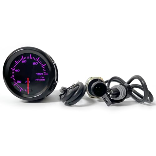
WHICH VEHICLES CAN THIS 52 MM METER FIT? This universal electric oil pressure gauge is compatible with 12 V cars and trucks. It fits standard 52 mm dashboard pods or steering column mounts seamlessly, providing a secure physical instrument setup.
Fix Your Ground: A Bad Ground Ruins Your Gauge
A bad ground is a common cause of fuel gauge failure, so start your troubleshooting there. A faulty ground can make your gauge read empty or full when it shouldn’t. Rust or corrosion at the sender’s mounting surface can break the electrical path, so thoroughly clean those contact points. Insulation issues in the ground wire can also interrupt the return circuit, leading to erratic needle movements. If your tank is isolated by rubber or nonconductive parts, you’ll need to run a dedicated sender-to-chassis ground. A ground loop, where current takes an unintended path, can also affect accuracy. To fix this, run a separate ground wire from the sender housing to the vehicle frame. Use a multimeter to check continuity and ensure a solid ground connection. A clean, direct ground is essential for accurate gauge readings. For boaters, ensuring a reliable ground is just as critical as choosing the best speedometer for boat from a trusted review.

【8 Gauge Power Ground Wire】: 8ga bulk wire is one of the most important products for all your wiring needs. Ideal for car amp, subwoofer, automotive system, car radio, RV trailer, lighting, speaker, ground wire, power cord, Amplifier, solar panel projects, welding cable and more.
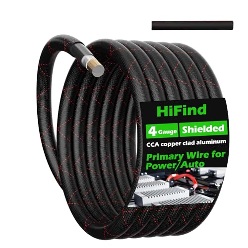
Shielded High-Quality Power Transmission: Made with high-quality 4 AWG Copper-Clad Aluminum (CCA) to ensure superior and stable power transmission. Featuring an aluminum foil shielding layer, it resists electromagnetic interference, unlike the common unshielded cables in the market. The copper-clad aluminum design is both lightweight and flexible, making it suitable for various high-efficiency power transmission needs, especially in automotive, home theater, and radio devices

✅【8 AWG Power/Ground Wire】High quality, 8 gauge power/ground wire meets American Wire Gauge(AWG) standard,offering true-to-gauge quality that guarantees the necessary power flow for your wiring projects
Test Everything Before You Button It Up
Before reinstalling the float switch, thoroughly inspect it for corrosion, broken wires, or bent float arms. If the electrical readings are outside the specified range, do not reinstall the unit; replace it instead. Confirm that electrical contacts are secure and that the float arm moves smoothly through its mechanical sweep. Use a multimeter set to ohms to measure resistance changes as you move the float arm, verifying the sender unit accurately corresponds to tank level. Adjusting your sensitivity and ping speed can help isolate the signal from the float arm’s movement, just as it clarifies bottom detail on a fish finder. Additionally, typical failure signs include inaccurate fuel gauge readings or a gauge that stays on empty. Taking these steps now prevents the need for draining the tank later and ensures reliable operation. You can also cross-reference the sender’s resistance values with the chartplotter display to confirm compatibility before final assembly.
Why Your Fuel Gauge Reads Empty, Full, or Not at All
A faulty sender or wiring is the most common reason your fuel gauge reads incorrectly or not at all. Open circuits in the sender wire—such as broken wires, corroded terminals, or unplugged connectors—interrupt the signal to the gauge, often causing it to read empty. If the float inside the sender is stuck or broken, it can freeze the needle at full or empty, while worn-out resistor tracks or bad wipers inside the sender can create dead spots or total signal loss. Ground issues also distort readings: a missing sender ground can make the gauge read full, whereas a missing ground at the dash can cause it to read empty. A faulty gauge cluster itself can give false readings even if the sender and wiring are fine. Always verify sensor calibration and electrical compatibility when replacing components, as mismatched parts can lead to inaccurate readings. If the sender tests good but the needle remains stationary, the issue likely lies in the wiring or instrument cluster. Understanding the resistor tracks and wipers inside the sender is key to diagnosing dead spots or total signal loss. For noise-free signal transmission, consider using a shielded transducer cable designed to block electrical interference. Using a digital multimeter to test resistance across the sender terminals can confirm if the sender float moves smoothly through its range.

CROSS-REFERENCE WITH 15306349, 1627 PTA1692 1627 S1410 PT909 EC908 PT1402 0 0

Durable outer coverings help shield and protect against tough conditions, vibration, abrasions, and moisture

Wire Harness Length:10CM