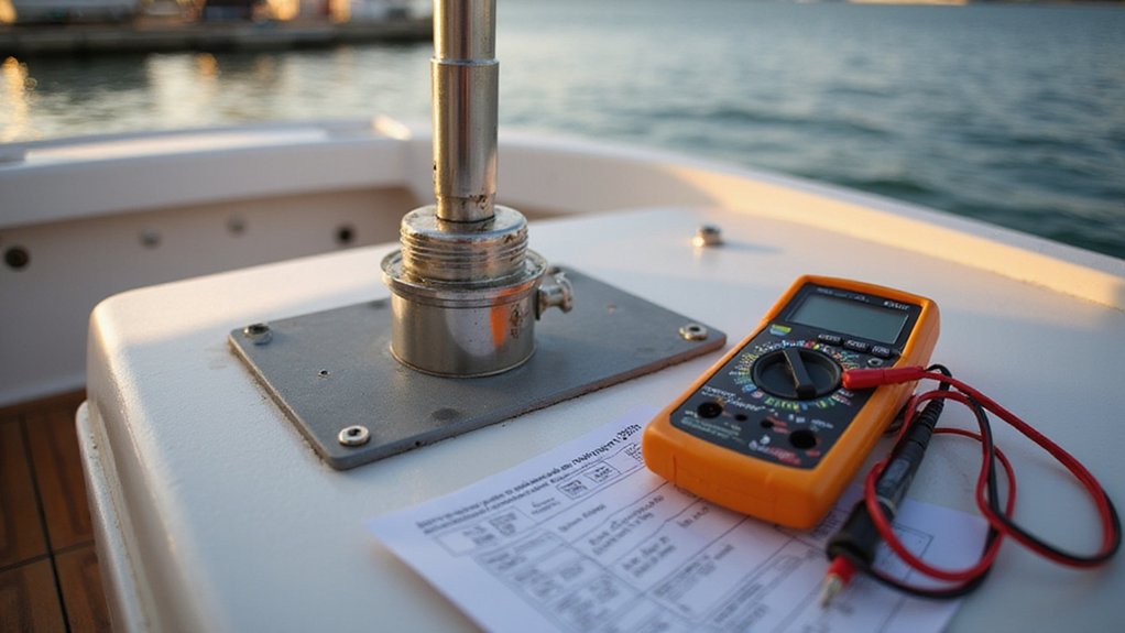
Ever wondered how to check if your boat’s fuel gauge is working right? The answer lies in testing the fuel sending unit, which tells your gauge how much fuel is in the tank.
By using a multimeter, you can quickly identify if the sender is faulty or if wiring issues are at play. Keep reading to learn how to do it step-by-step and get your gauge reading true again.
Know Your Sender’s Ohm Range Before Testing
Knowing your sender’s ohm range before testing is crucial. Most senders have a specified resistance range, and testing blindly can lead to confusion or incorrect conclusions. U.S. marine senders typically measure 33 ohms when full and 240 ohms when empty. European VDO systems flip that, with around 10 ohms empty and 180 ohms full. Always verify the exact resistance range for your specific sender to ensure electrical compatibility. Using the wrong range or gauge can produce misleading readings or result in a half-tank error, making it appear as if the sender is faulty when it’s not. This echoes the importance of choosing the right gear, much like selecting the best marine antenna for reliable communication. For those seeking a reliable replacement, reviewing the best fuel tank sending units can clarify which models match your boat’s system. Similarly, checking that your horn button functions correctly avoids signaling issues when troubleshooting electrical components.
To get accurate measurements, check the brand and part label for the rated empty and full resistance values before testing. Recording these values as a baseline helps interpret your multimeter readings. A functioning sender’s resistance will sweep smoothly across its expected curve, rather than jumping erratically. Testing without knowing this target range risks turning a simple diagnosis into guesswork, which may lead you to replace parts unnecessarily. Properly identifying the ohm range saves time, money, and frustration.

Great marine fuel sending unit replacement for broken boat fuel sending unit in marine boat fuel tank.

Great marine fuel tank sending unit replacement for broken marine fuel sending unit in marine boat fuel tank.

<b>[A Direct Replacement Sending Unit]</b> Sucicago Reed Switch Diesel Fuel Water Level Sensor is a Better Option Than the Traditional Lever Type Sensors. The Boat Fuel Tank Will not Effected by The Constant Movement Caused by Waves and Boat Rocking. <b> It Will give an Accurate Indication of Fuel Level and the Fuel Gauge No Longer Bounces All Over The Place In Windy Wave Situations.</b> <br>
Set Up Your Multimeter for Fuel Sending Unit Testing
To test your fuel sending unit with a multimeter, set it to ohms (Ω), choosing the lowest resistance range for better resolution. First, disconnect the sender plug to isolate it from the gauge circuit. Place one probe on the signal terminal and the other on the ground terminal, or on the sender body if it grounds through the tank. Clean the probe contact points to prevent corrosion from affecting readings. Ensure your meter displays a stable reading before proceeding. Adjusting the frequency and ping speed can also help filter out interference when interpreting sonar returns, similar to how you refine resistance measurements.
Verify that your multimeter reads near zero when the probes touch, confirming its calibration accuracy. Follow safety precautions by keeping the sender electrically separated from the boat wiring. Never test in voltage mode; this can damage both your meter and the sender. Use the continuity setting solely to check wiring faults, not the sender’s resistance range. If you see OL or erratic readings, recheck your resistance range and probe contact points. Using a multimeter, you can identify the resistance type by comparing the readings to known American or European values. This process is different from using a fish finder’s sonar technology, which relies on sound pulses to map underwater objects. For a more complete boating electronics setup, you might also consider a Lowrance Eagle 7 unit that provides detailed sonar mapping.
How to Bench Test a Fuel Sending Unit Float Arm
To bench test a fuel sending unit float arm, begin by positioning the sender exactly as it sits in the tank—upright and with the float arm free to move. First, check the float arm movement: it should glide smoothly from its lowest to highest position without grinding, sticking, or stalling. Any hesitation indicates mechanical issues such as wear, corrosion, or deformation. Inspect the pivot point for rust, dirt, or debris, and consider applying light lubrication to ensure frictionless movement. Never bend or alter the length of the float arm, as doing so can distort the gauge readings. Confirm that the float itself is intact and buoyant; a compromised float will give inaccurate readings. This mechanical inspection is crucial because a binding or stiff arm will produce false electrical resistance readings, regardless of the sender’s internal condition. For anglers who fish from shore, similar precision is needed when choosing a fish finder for accurate depth tracking. Selecting a top-rated switch panel can help organize all related electrical testing equipment for your boat. For comparison, Garmin chartplotters with HDMI output offer superior display clarity that highlights the importance of precise data input.

【US Standard output】: Fuel sending unit are suitable for American standard output 240-33 ohms (240 ohms empty, 33 ohms full). Fuel sending unit made of high quality aluminum alloy, rubber and plastic, corrosion resistance, stable output signal, long service life, accurate measurement.

All swing arm readings are subject to fuel-slosh fluctuations

Trendy and unique sport accessories.
Step-by-Step Fuel Sending Unit Testing at Tank Positions
To test a fuel sending unit at tank positions, follow these steps to ensure its accuracy and consistency. First, disconnect the sender wires at the tank to prevent feedback into the gauge circuit. Set your multimeter to measure resistance (ohms) and identify the signal and ground terminals on the sender.
Begin at the empty tank position. Move the float to its lowest point—American marine senders typically read around 240 ohms. Record this reading. Next, check the quarter-tank position; expect roughly 150 ohms. Then, test the half-tank position, which should be approximately 100 ohms. At three-quarters, readings are usually near 70 ohms, and at full tank, about 30 ohms. Ensure that the resistance readings change smoothly between these points without unexpected jumps. Making clean, reliable connections with the multimeter and sender terminals is essential for accurate readings, much like ensuring proper wiring in a horn relay setup. Using the multimeter with alligator clamps can make these connections easier and more reliable. For improved nighttime visibility of your testing area, consider installing courtesy lights to avoid accidental short circuits. A binnacle compass also requires smooth resistance changes in its internal components to function accurately on a boat.
If your measurements deviate significantly from these values, it indicates the sender may need replacing. Consistent and smooth readings across all tank positions confirm proper calibration of the fuel gauge, ensuring it accurately reflects the actual fuel level.

[High Precision and Long Life]: The exterior is made of stainless steel, and the interior is controlled by high-quality reed switches. The sensor is corrosion-resistant, does not rust, has a long life, stable output signal, and accurate measurement. Suitable for gasoline, diesel, water, methanol, etc.

Calibrated to the Industry Standard of 33-240 Ohms

Provides accurate fuel level information
5 Bad Readings and What They Actually Mean
When your fuel sending unit produces bad readings, those numbers are clues to its condition. An OL (open circuit) reading indicates the internal track is broken, meaning the sender needs to be replaced. A zero-ohm reading points to a short inside the sender rather than a wiring problem. For US-standard units, resistance outside the range of 232–252 ohms when empty or 28–36 ohms when full signals a faulty sender. Erratic, jumping, or frozen readings suggest worn internal contacts or a stuck wiper—it’s time to replace the unit. If the resistance changes but never reaches the proper endpoints, the sender may be mechanically limited or out of calibration, leading to inaccurate readings even though it isn’t completely dead. For example, if you measure around 45 ohms at a half tank, you can use judgment to determine if that reading fits the estimated fuel level. Interpreting these signals is much like reading a fishfinder display, where understanding key settings on your depth sounder prevents false bottom readings. Applying this same logic, you can avoid misinterpretation by checking for a false bottom reading caused by debris or thermoclines. Similarly, just as low oil pressure can indicate a failing pump or clogged passages, a faulty sender will not provide the correct resistance for the actual fuel level.
How to Tell If It’s the Wiring or the Sender Itself
To determine if the fuel gauge issue is caused by the wiring or the sender itself, start by disconnecting the sender wires at the tank. Use a multimeter to measure resistance across the sender terminals while moving the float. A functioning sender will show resistance that smoothly changes through its full range. If the resistance remains infinite or shows no change as the float moves, the sender is faulty and needs replacing. To ensure the sender is mounted securely for accurate readings, consider following a DIY fish finder mount approach to stabilize the sender installation. For a more precise understanding, note that a pitot tube measures dynamic pressure to determine water speed, which is unrelated to fuel level but highlights the importance of using the correct sensor for each system. A night vision camera for your boat uses infrared or thermal imaging to enhance visibility in low light, which is a separate system from fuel level sensors.
Next, test the wiring for continuity. Disconnect the sender wire at both the sender and the gauge. Measure resistance; a good wire should read under 2 ohms. Resistance higher than that indicates corrosion or damage, requiring wiring repair. Also check for shorts to ground—if the wire shows infinite resistance, it’s not shorted. If the wire tests fine but the gauge still misreads, then the problem likely lies with the sender or the gauge itself, not the wiring.