Dealing with a faulty fuel gauge can be frustrating, especially when you’re unsure if it’s the sensor or wiring at fault. Luckily, you can troubleshoot and potentially fix the issue yourself without much hassle.
By understanding the steps involved, you’ll be able to identify and repair common problems with the fuel sending unit.
Stay with me as I lay out the full repair process step by step.
Diagnose a Stuck Fuel Gauge Before Opening the Tank
You can often diagnose a stuck fuel gauge from the driver’s seat without opening the tank. Begin by observing the needle’s behavior: does it remain fixed at full, empty, or mid-tank? If it moves when you hit bumps, that indicates an intermittent electrical fault. Cross-check the dash reading with your estimated fuel consumption; a single inconsistent reading doesn’t prove a problem, but repeated sticking points suggest an issue.
Next, inspect the fuse for the fuel gauge circuit and verify that the instrument cluster powers up when you turn on the ignition. Use a scan tool to check for fault codes related to the cluster. Proceed with wiring tests: look for corrosion or damage in the sender harness and ensure the chassis ground near the sender is secure. A poor ground can cause false readings. Before opening the tank, use a multimeter to confirm that the gauge circuit voltage is within specifications. Using a quick reset method of turning the ignition on and off several times can often resolve the issue without tools. For boat owners, choosing a top fish finder for boats can help you locate underwater structure and fish, complementing your fuel management. For boat owners, ensuring a secure mounting position for the sender unit prevents future grounding problems. Additionally, installing a waterproof hour meter near the sender can help track engine runtime for better maintenance scheduling.
Prep Your Car Safely for Fuel Sender Repair
To safely prep your car for fuel sender repair, start by parking on a flat, level surface and setting the parking brake firmly. Place wheel chocks at the front and rear wheels to prevent movement. Shift the transmission to Park or Neutral, then turn off the engine and remove the key to prevent accidental starting.
Disconnect the negative battery cable immediately to cut power to the fuel system. This safety step minimizes the risk of sparks igniting fuel vapors. Next, disable the fuel pump by removing its fuse or relay, then crank the engine briefly until it stalls to relieve fuel system pressure. Do not loosen any fittings to vent pressure, as this can be dangerous. Understanding depth finder technology can help you choose a more accurate marine fuel gauge for your boat.
Ensure your work area is well-ventilated and free of ignition sources like open flames or sparks. Keep a Class B fire extinguisher nearby in case of emergencies. Wear safety glasses and fuel-resistant gloves to protect your eyes and skin. Have a fuel-safe container ready to catch any drips, and treat any spilled fuel as a fire hazard until it is thoroughly cleaned up. A reliable speedometer for boat can also help you monitor your vessel’s performance while troubleshooting fuel issues. Consulting a fuel tank sending unit guide can help you verify the correct replacement part for your vehicle.
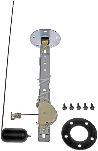
Direct replacement - this fuel tank sending unit is designed to match the fit and function of the original unit on specified applications

[Part Number] E5TZ-9J306-BA (Fuel Filter); E53Z-9H318-A (Control Valve Assembly); E6AZ-9C385-A (Retaining Ring); E1VZ-9417-B (Gasket); 4C4Z-9365-BA (Fuel Filter Element)

【Fuel Sender Material】: Fuel sending unit is made with heavy duty stainless steel. This water level sensor is reed switch, durability and reliability, steady output signal. No adjustment needed for tank.
Remove the Sending Unit Without Damage
To remove the sending unit without damaging it, begin by thoroughly cleaning the area around the opening to prevent contamination. Disconnect the fuel lines and electrical connectors in a controlled order, marking each pair and capping open lines to minimize spills. Use a non-sparking tool to carefully remove the retaining ring, turning bayonet-style rings counterclockwise and lightly tapping the ears to avoid bending the lugs. If the ring resists, switch to a more aggressive stance after attempting a gentle approach, as patience and method are critical. Testing the unit beforehand with a multimeter can identify incorrect resistance readings that confirm failure. For precise audio feedback while working, consider using marine Bluetooth speakers that are built to withstand marine environments. You can reference a downloadable software update guide to ensure your diagnostic equipment is running the latest firmware for accurate readings.
Once the ring is fully removed, pull the sending unit straight out, guiding the float arm carefully through the tank opening. Take care not to bend the float wire or arm during removal. Be mindful of internal tank edges that could snag or damage the assembly, and move slowly to protect the sender body. After removal, carefully remove any old gasket or O-ring without gouging the sealing surface, keeping the tank opening covered to avoid dirt or debris entry. Store the sender safely before inspection to prevent damage.

WATER RESISTANT: This is a marine speaker with water resistant construction and can be used for several vehicles because it can withstand heavy water splashes and other outdoor conditions
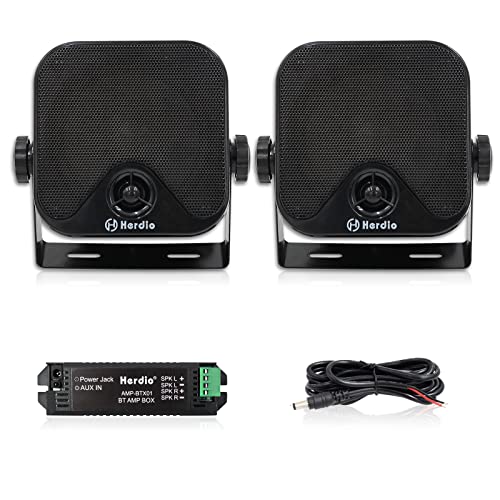
5.0 BLUETOOTH CONNECTIVITY : No player required,Bluetooth wireless streaming receiver for a simple connection .Works with any bluetooth device.The Bluetooth coverage can reach 65 ft , Wherever you are in the courtyard,boat,swimming pool you also can enjoy a high bluetooth definition sound

WALL MOUNT SPEAKERS FOR INDOORS/OUTDOORS – Upgrade your listening experience with these 6.5'' wall mount speakers. Delivering 30 watts of peak power, they are suitable for outdoor patios, pool areas, or enhancing your home audio system.
Inspect the Fuel Sender’s Float, Wiper, and Track
After removal, inspect the fuel sender’s float, wiper, and track carefully to identify common failure points before reassembly. Check the float for cracks, fuel intrusion, or dents; it must remain buoyant and maintain proper fuel level readings. Confirm the float arm moves freely without binding or rubbing against the tank walls. Next, examine the wiper for contact corrosion, oxidation, or wear—any weak pressure against the resistor track can cause erratic fuel gauge readings. Inspect the resistor track itself for scoring, cracks, or burned sections that could interrupt the circuit. Look for dead spots where resistance jumps or opens, which can affect accuracy. Also, verify the wiper mounting isn’t loose or damaged. If you notice contact corrosion, physical damage, or a broken track, replace the entire sender assembly for the most reliable operation. Similar to troubleshooting a fish finder, verifying the resistor track for continuity helps ensure accurate signal transmission. For marine applications, ensuring a clean electrical path is as critical as selecting a quality performance transducer for precise underwater readings. Always check for updated software files to maintain consistent performance across interconnected marine electronics.

Great marine fuel sending unit replacement for broken boat fuel sending unit in marine boat fuel tank.

Venom Brand fuel baffle float repair kit. It fits ALL year, models & engine sizes of carbureted Sea-Doo watercraft & jet boats with a fuel gauge. NOTE: For carbureted models ONLY, will not fit DI, RFI & 4-Tec models.

Great marine fuel tank sending unit replacement for broken marine fuel sending unit in marine boat fuel tank.
Bench-Test the Fuel Sender for Smooth Resistance
Bench-testing your fuel sender involves verifying smooth resistance changes before reinstalling it. First, disconnect the sender from the vehicle wiring to isolate the circuit. Remove the unit, clean it, and position it in its in-tank orientation. Set your digital multimeter to the ohms range, such as 200 ohms. Connect one lead to the signal terminal and the other to the sender’s ground point or body. For consistent testing, ensure your multimeter leads make solid contact, similar to checking high-quality marine speakers for reliable connectivity. Using a tool like a side imaging fishfinder can help visualize the internal structure of the sender for precise testing.
Next, slowly move the float arm from empty to full. Observe the meter readings for a steady, continuous change in ohms—no sudden jumps or dips. A smooth transition indicates proper electrical continuity and resistance accuracy across the entire range. Typical resistance ranges include 0–90 ohms for GM-style fuel senders and 73–10 ohms for Ford units. If you notice dead spots, spikes, or no change at all, the sender is faulty. Finally, compare your readings at the empty and full endpoints with the specifications listed in your vehicle’s service manual. Ensuring the resistance range matches the gauge’s specified values is critical for accurate fuel level readings. A dependable testing approach demands stable connections, similar to how catfish anglers rely on consistent sonar performance for accurate depth readings.
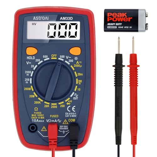
Additional Tips - The following incorrect operations may cause the multimeter not to show results: Firstly, the plugs of test leads are not fully inserted or not inserted into the correct sockets. Secondly, the manual rotary switch is not placed in the correct position. In addition, this meter can not test all AC Current and below 100mV AC Voltage. Please check the user manual carefully before measurement.

Versatility: ANENG multi meter is a highly adaptable electronic tool that can be used to measure a wide range of electrical properties, including AC/DC voltage, current, resistance,continuity,diode and Live wire.This makes it an essential tool for anyone working with electronics or electrical systems,also widely used by hobbyists, students, and professionals in various fields, including engineering, automotive repair, and electricians.
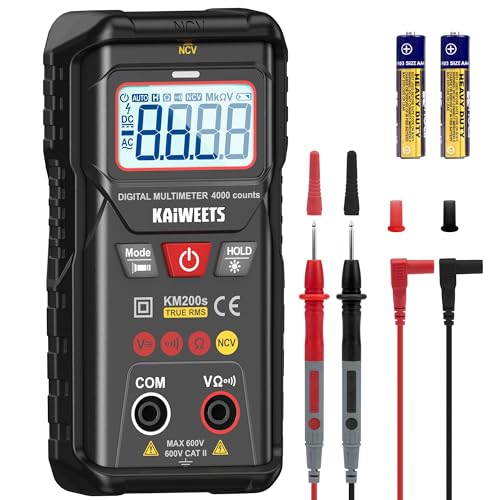
Smart Measurement: With smart auto ranging mode, the KM200s multimeter instantly recognizes and switches between AC/DC voltage, resistance, and continuity—no dial, no range, no guesswork. Measure faster, easier, and more accurately every time.
Reinstall and Verify Gauge Response and Leaks
Reinstall the sender carefully, ensuring the float arm can move freely inside the tank without hitting baffles or the tank wall. Match the gasket hole pattern exactly, then tighten the screws in a star pattern. This evenly seats the seal and prevents distortion of the housing. Reconnect the sender wire and confirm a solid ground path by checking electrical continuity between the sender body, tank, and chassis. Poor grounding often causes false gauge readings, so thorough troubleshooting is essential. Beginners should treat the display clarity of their fish finder as equally critical to ensuring accurate readings on the water. However, understanding how a boat speedometer works requires a similar focus on pressure-based readings from the pitot tube to ensure reliable speed data. Similarly, investing in a high-performance night vision camera can dramatically improve situational awareness during nighttime navigation. Turn the ignition on and observe the gauge’s response; moving the float through its travel should produce a smooth needle movement. To calibrate, first check the gauge at approximately half a tank; if it reads low, slightly bend the float arm downward. If it reads high, bend the arm upward. After calibration, refill the tank and perform a leak test by applying soapy water around the flange—bubbles indicate leaks. Tighten the screws again in a star pattern and retest until no bubbles form. Confirm that the gauge accurately reflects the actual fuel level for a proper repair. Use a multimeter set to ohm mode to verify the resistance readings align with the estimated fuel amount, ensuring the sender’s resistance matches the expected range for a half tank.

【Excellent Fit】: This fuel sender gasket kit complete with fine / course replacement screws and washers. Our fuel tank sender gasket has 5 holes for electric and mechanical fuel sending units

Wide Compatibility: This fuel tank sending unit gasket fits plastic or metal fuel tanks in boats, marine vessels, trucks, and RVs, offering a universal replacement for fuel sender applications

SAE 5 hole gasket 5 mounting screws with washer