Having trouble with a faulty fuel gauge? You might be surprised to learn how simple it can be to fix yourself.
By replacing the fuel sending unit, you can restore accuracy and avoid costly repairs at the shop.
In this guide, you’ll learn step-by-step how to safely remove the old unit and install a new one, ensuring your fuel readings stay true.
Keep reading to see how you can tackle this project with confidence.
Why Your Fuel Gauge Is Wrong and How to Fix It
The primary cause of a faulty fuel gauge is often the fuel sending unit inside your tank. Worn resistor tracks can create dead spots, causing the needle to stick or jump unexpectedly. Other issues like a stuck or fuel-logged float, bent sender arm, or contamination can also distort readings significantly. Upgrading to a modern unit can improve accuracy, just as top fish finders for boats offer enhanced reliability for anglers. Similarly, choosing a sender with a proven track record can prevent recurring gauge failures, much like selecting reliable speedometers helps ensure dependable performance on the water. Investing in a quality unit with advanced sonar capabilities can even help you avoid hitting submerged obstacles that might damage your fuel system.
Before taking anything apart, check your wiring and grounds. Corroded connectors, broken wires, or a poor tank-to-frame ground are common sources of false signals. Ensuring proper electrical compatibility between the sender and gauge system is essential for accurate readings.
To fix the problem properly, perform a basic fuel gauge calibration. Measure the sender resistance at both empty and full tank levels. If the resistance values fall outside the manufacturer’s specifications, replace the sender instead of trying to adjust it. Cleaning existing connections and improving ground connections can often resolve false signals without the need for replacement. Always isolate the faulty component first before proceeding with repairs.
Tools and Parts You’ll Need for the Sender Swap
You’ll need a socket set with 8 mm, 10 mm, and 14 mm sizes. These are common sizes for fuel tank components and fasteners, so having them on hand ensures you can remove and reinstall parts without delays. Flat-head and Phillips screwdrivers are essential for prying access panels, loosening screws, and removing retaining rings. Groove-joint pliers help with gripping and twisting stubborn fittings, while a non-ferrous punch is necessary for carefully removing retaining rings without damaging surrounding parts. For the fuel sending unit, get an exact-match replacement to ensure proper gauge readings. Double-check compatibility because mismatched resistance ranges cause inaccurate fuel level displays. Consider aftermarket units but verify they include a new gasket or O-ring and a replacement lock ring if corrosion is present on the originals. Keep extra screws, washers, and fuel line clips on hand for reassembly, ensuring everything fits securely. Don’t forget shop rags and gloves for safety, a shop vac to clean debris, and a multimeter to check electrical continuity and circuit health before putting everything back together. For beginners learning to work with similar electronic devices, top fish finder options often include simple wiring and resistance checks to verify accuracy before use. A marine radio with remote mount can similarly simplify wiring and placement tasks by allowing remote station control from a separate helm location. Understanding the horn relay location in your vehicle can help you trace electrical circuits more confidently during similar troubleshooting tasks.
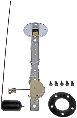
Direct replacement - this fuel tank sending unit is designed to match the fit and function of the original unit on specified applications

[Part Number] E5TZ-9J306-BA (Fuel Filter); E53Z-9H318-A (Control Valve Assembly); E6AZ-9C385-A (Retaining Ring); E1VZ-9417-B (Gasket); 4C4Z-9365-BA (Fuel Filter Element)

【Fuel Sender Material】: Fuel sending unit is made with heavy duty stainless steel. This water level sensor is reed switch, durability and reliability, steady output signal. No adjustment needed for tank.
Safety Steps: Disconnect the Battery and Ventilate the Area
Disconnecting the battery and ventilating the area are essential safety steps before replacing a fuel sending unit. First, turn off the ignition to ensure the vehicle is completely powered down. Then, disconnect the negative battery cable first to prevent electrical sparks that could ignite fuel vapors. Keep the cable isolated to avoid accidental reconnection, which could cause a spark. Never skip this step, as electrical arcs near gasoline pose a serious fire risk.
Next, ventilate the workspace thoroughly. Ideally, work outdoors or in a well-ventilated area to prevent fuel vapor buildup. Open doors and windows, and avoid working indoors if possible. Keep all sources of ignition away—no smoking, open flames, or spark-producing tools. Having a Class B fire extinguisher nearby adds an extra layer of safety. These precautions help eliminate the risk of ignition, keeping you safe while you handle the fuel sending unit. For a similar workspace upgrade, consult a review of top depth finders to choose a reliable unit for your boat. For even greater peace of mind during marine installations, consider pairing your safety setup with Garmin Echomap Ultra 106sv reviews for reliable navigation equipment.
Removing the Old Fuel Sending Unit Without Damaging the Tank
To remove the old fuel sending unit without damaging the tank, start by draining enough fuel to lighten the tank and reduce the risk of spillage. Label and disconnect the electrical connectors and fuel lines carefully to avoid mix-ups or damage. Keep the work area clean to prevent dirt from falling inside once the opening is exposed. Ensure the fuel tank is drained before removal to minimize hazards. For accurate readings later, adjusting the screen readouts on your fish finder can help interpret sonar returns while you work. To ensure reliable connectivity on the water, consider choosing marine Bluetooth speakers that resist moisture and vibration. A binnacle compass, for instance, uses a magnetic card that remains level regardless of the boat’s motion, ensuring steady directional readings.
Identify the locking mechanism—whether it’s a lock ring, screws, or a threaded retainer. Turn bayonet-style rings counterclockwise, using controlled taps with a suitable tool to prevent deformation of the tank opening. If the ring is stuck, apply penetrating oil solely to the metal threads, avoiding plastic parts to prevent damage. Slowly and evenly lift the sender, ensuring the float arm does not snag on baffles or other tank structures. Pause periodically to allow trapped fuel to drain back naturally. Remove the old gasket and inspect the opening for debris or corrosion. Cleaning the tank opening thoroughly before installing the new sender ensures proper calibration later.

【Excellent Fit】: This fuel sender gasket kit complete with fine / course replacement screws and washers. Our fuel tank sender gasket has 5 holes for electric and mechanical fuel sending units

Great marine fuel sending unit replacement for broken boat fuel sending unit in marine boat fuel tank.

Great marine fuel tank sending unit replacement for broken marine fuel sending unit in marine boat fuel tank.
Measuring Tank Depth and Adjusting the Float Arm
Match the float arm length to your tank’s measured depth. If the exact depth isn’t listed, select the next highest size and trim the arm accordingly. Slide the float and its hardware until the outer end is about 5/16 inch shy of the arm’s specified dimension. Carefully mark the arm where you will cut it later to ensure an accurate fit. A fuel sending unit uses a variable resistor to translate float position into an electrical signal for the gauge.
Ensure the float arm can rotate freely without hitting tank walls, baffles, or internal obstructions. Some sender units allow a 90-degree rotation for better clearance. The goal is to position the float close to the tank bottom without making contact, so your low-fuel reading remains precise. For instance, treat transducer placement with similar care to avoid errors in sonar data. Proper alignment and fitting prevent inaccurate readings and prolong the lifespan of your sender. For cross-referencing fuel levels with navigation, a chartplotter can display tank data alongside accurate depth readings from the sender.

【US Standard output】: Fuel sending unit are suitable for American standard output 240-33 ohms (240 ohms empty, 33 ohms full). Fuel sending unit made of high quality aluminum alloy, rubber and plastic, corrosion resistance, stable output signal, long service life, accurate measurement.

Product includes: You will receive 2 fuel level floats, which can be used as replacement parts, can meet the needs of one replacement, and reserve spare parts to deal with sudden failures. There is no need to place an order separately again, which balances practicality and high cost-effectiveness, and is suitable for various scenarios such as families and repair shops

Replacement installs on float arm of the fuel sending unit
Set the Float Arm for Perfect Clearance on Your New Sender
To set the float arm for perfect clearance, start by gradually bending the arm instead of creating sharp kinks. This preserves the intended arc while allowing the float to clear obstructions. If your sender design permits, reposition the float on the arm to adjust the overall length and achieve proper clearance. After each bend or rotation, perform a clearance verification by moving the float through its full range by hand. Verify that it travels smoothly and freely at both the high and low ends of its swing. If it sticks or encounters resistance, repeat the adjustment process until the float moves without hesitation. Simply follow the same principle used when selecting a weatherproof cover to keep components dry and functional. Getting the orientation wrong can introduce errors similar to those seen when a sonar transducer is poorly aligned, so ensure your float arm follows a consistent arc. For a reliable installation, paying attention to this arm alignment is as critical as choosing the right transducer type for your fish finder.
Installing the New Gasket and Sender Without Leaks
To prevent leaks when installing a new sender, thorough preparation is essential. First, clean both sealing surfaces completely, removing every trace of old gasket material with a plastic scraper. Wipe the tank flange and sender base with a lint-free cloth to remove fuel residue, dirt, or rust. Inspect both surfaces for dents or distortion that could compromise the seal. Matching the gasket precisely to your sender design is crucial; if it’s cork, cut it cleanly to follow the flange opening and punch bolt holes accurately. Place the gasket flat on the sender without twisting or pinching. When lowering the sender into position, ensure the gasket remains seated evenly and doesn’t roll or hang into the tank. Use proper sealing techniques at fastener points—install sealing washers where specified and replace any rubber washers meant only for one-time use. Before performing a leak test, confirm that the seal sits uniformly around the entire flange. For a clean and reliable installation, follow the same principle of careful wiring and mounting practiced with marine electronics.

Wide Compatibility: This fuel tank sending unit gasket fits plastic or metal fuel tanks in boats, marine vessels, trucks, and RVs, offering a universal replacement for fuel sender applications

SAE 5 hole gasket 5 mounting screws with washer

Fuel Sender Replacement: Replacement gasket is made for compatible Seachoice fuel senders.
Tighten Sender Screws Properly to Avoid Leaks
Start all sender screws by hand before applying torque to ensure the unit seats evenly against the flange. This helps prevent uneven load distribution that could distort the flange and cause leaks. Tighten each screw in a cross-pattern sequence to promote uniform gasket compression. Use about 15 to 25 inch-pounds of torque; over-tightening can strip threads or crush the gasket, ruining the seal. Proper gasket compression allows the seal to squish slightly without bulging out. For added thread protection, apply a fuel-resistant sealant to the screws, but make sure each hole accepts a screw normally before final tightening. If the gasket begins extruding, you’ve tightened too much. After tightening, confirm that the sender sits flat against the tank surface and perform a leak test before completing the installation. Just as a blocked pitot tube can cause critical gauge failure at sea, a faulty sender seal here can lead to dangerous fuel leaks or inaccurate readings. For optimal visibility in dark compartments, consider pairing this installation with low-glare LED courtesy lighting to spot any drips or seepage around the sender flange during the leak test.

Durable Construction: The boat fuel sending unit gasket is made from high-quality materials, ensuring longevity and providing a reliable seal for your fuel tanks and water tanks

Two-Pack Replacement Kit:The package includes two pieces of the fuel tank sending unit gasket. This two-pack provides a convenient solution for maintenance needs or for having a spare fuel pump gasket and boat gas tank cap gasket on hand

Resistant to gasoline and all other automotive fluids
Reconnecting Wires and Testing Your Fuel Gauge Accuracy
To guarantee your fuel gauge reads accurately after installing a new sending unit, follow these steps carefully. Start with the ignition off to prevent false readings. Match each wire to its labeled terminal on the new sending unit, ensuring correct connections. Before plugging in, inspect the terminals for corrosion or bent pins, as these can cause poor contact and inaccurate readings. Verify that the sender body has a clean ground path to the chassis; aim for a resistance of zero ohms, indicating a solid ground. Ensuring the sender’s resistance range matches your gauge’s specifications is essential for accurate fuel level readings.
Next, measure the sender’s resistance range at both empty and full positions. The resistance values should match your gauge’s expected specifications—mismatched ranges can lead to reversed or erratic readings. Record the ohms at both positions for comparison. To test calibration, disconnect the signal wire and ground it; the gauge should then read empty. If it doesn’t, there’s likely an open circuit. For a full sweep test, gradually move the float while monitoring resistance changes—look for smooth variations without dead spots. Avoid troubleshooting wireless transmission here, as grounding the wire provides a more reliable method for isolating faults. After reinstalling the tank, double-check the ground connections, as vibrations from driving can loosen them over time.
Common Mistakes That Ruin a Fuel Sender Installation
Even when you’ve selected the correct fuel sender, avoiding common installation mistakes is crucial for reliable operation. Installing the sender upside down or with the float side reversed will cause your gauge to read backward, giving you false readings. Match the float arm length to your tank’s depth, and trim it carefully to prevent inaccurate empty or full signals. Be sure the arm swings freely—don’t bend it or force it past tank baffles, as contact or binding can impair movement.
Poor sealing is a common issue. Dirty mounting surfaces or reusing gaskets can lead to leaks, and over-tightening the flange causes distortion that compromises the seal. Ensure your ground connection is clean metal-to-metal; any paint, rust, or corrosion will disrupt the electrical path and throw off calibration. Lastly, consider your tank’s material when choosing sealing components. Use only compatible gaskets and thread sealers to avoid vapor wicking, which can cause inaccurate readings or fuel evaporation. By avoiding these pitfalls, your fuel sender will deliver consistent, accurate performance.