If you’re wondering how to properly install a transducer on your trolling motor for the best sonar readings, you’re in the right place. The right setup ensures accurate depth measurements and stable images, so getting it right matters.
Keep reading to learn step-by-step how to mount your transducer safely and correctly for optimal performance.
Why Your Mounting Choice Matters More Than You Think
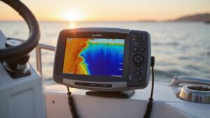
A proper mounting location is crucial because it minimizes sound wave interference from the propeller. If the transducer is placed too close to the propeller’s water path, cavitation can occur—this is when bubbles form and collapse, creating noise that disrupts sonar signals. Such pressure disruptions weaken the sonar’s ability to send and receive clear returns, reducing detection accuracy. For similar precision, maritime regulations specify exact stern light height to ensure compliance and safety on the water. On the Garmin Striker 4 screen, bait balls and fish arches appear as distinct sonar signatures that help you differentiate real fish from clutter. Additionally, selecting a model with high CHIRP sonar frequencies provides clearer target separation in deep water.
To avoid this, position your transducer away from the propeller’s rotation side, following the manufacturer’s specifications. Make sure to offset the mount sufficiently, ensuring it does not fall into the propeller’s water disturbance zone. Correct placement helps maintain sonar clarity and protects your motor’s efficiency by preventing cavitation. Remember, a well-placed mount not only enhances your sonar readings but also ensures your motor performs at its peak.
How to Inspect Your Trolling Motor Before Transducer Installation
Before installing the transducer, you must thoroughly inspect your trolling motor, starting with critical safety precautions. Disconnect the motor from all power sources and verify oxide or isolate the wiring before working on it. Treat the motor as energized until you have fully separated the battery leads to prevent accidental activation.
Secure the motor firmly to prevent shifting during handling. Examine the shaft for signs of damage, bends, or corrosion, as these issues can affect alignment and performance. Check the propeller area for clearance; ensure there’s enough space to avoid contact during operation. Confirm that the propeller nut is tight to prevent loosening or detachment. Selecting a top depth finder for your boat can help you choose a transducer with compatible features for your installation.
Plan the cable route to avoid sharp bends, pinch points, and moving joints that could strain the wiring over time. Inspect the existing wiring for wear, fraying, or corrosion, which could interfere with connectivity. Leave enough slack in the cable to allow full deployment of the motor without tension or strain, as proper routing ensures cables do not interfere with the motor’s rotation. Using a reliable mechanical gauge helps confirm the motor’s pressure readings are accurate after installation.
Finally, assess the motor body for a clean, flat mounting surface. Ensure you can position the transducer parallel to the bottom and far enough from the motor to minimize sonar interference. Make sure the placement does not block steering, the propeller, or other vital functions, and leave room for clamps and future access or adjustments.
Attach the Transducer to the Motor Body, Facing Away From the Propeller
Attach the transducer to the motor body facing away from the propeller. Before fastening, orient the mount so its narrow end points away from the propeller to avoid impact and sonar interference. Proper mounting angle is crucial; align the mount’s reference point directly opposite the propeller. If your system is shaft-mounted, use the orientation knob to adjust the angle until it’s correctly positioned. Slide the transducer into place on the motor body, ensuring a snug fit. Secure it using the provided hose clamps, feeding one through the mount’s slot. Tighten the clamp firmly to prevent twisting and ensure the transducer remains level. For best results, keep the software files up to date to avoid connectivity issues with the display. Route the cable so it exits upward, allowing it to rest on top of the housing when stowed. To achieve a reliable electrical connection, treat the transducer wiring like a fuel sending unit by ensuring no frayed strands touch the motor body. Finally, double-check that the narrow end still faces away from the propeller and that there is sufficient clearance for deployment. For a clean and reliable installation, use marine-grade sealant to waterproof all exposed connections.

🛥️[Product Overview] Stern Pad, Screwless Transducer Mounting Plate kit, Marine-Grade Transducer Mounting Board Hardware Kit.

Replacement: 1840201, MKR-15, 410150-1

Replaces Part Numbers: MKR-15 transducer mounting kit cross references part 1840201 and 410150-1, specially designed to install sonar transducer on the lower unit of Mi-nn Kota bow-mount or transom-mount trolling motors. Fits motor lower unit sizes: 3-1/4", 3-5/8", 4", 4-1/2"
Route and Secure the Transducer Cable to Avoid Pinching
To route and secure the transducer cable effectively, start by attaching the transducer firmly and leveling it. Then, guide the cable along the shaft using gentle fasteners like black electrical tape; avoid overtightening zip ties, which can crush the cable jacket. Leave at least a 10-inch service loop near rotating joints to accommodate full, free motion without tension. When securing cables along the mount, place loose zip ties at multiple anchor points to create a working loop and check movement clearance. Choosing a power source with sufficient run time and capacity is essential for reliable operation during long trips. For catfish anglers, selecting a sonar unit with enhanced target separation can help distinguish bottom-feeding fish from structure. For new anglers, selecting a model with a clear display and simple menus makes operation much easier.
Anchor the cable securely at the motor head, creating a rounded bend at the mount entry to relieve strain. Keep the cable clear of pinch points, particularly where the shaft or bracket compresses during stowing or turning. Ensure the cable stays away from the propeller and high-energy wiring to prevent abrasion or electromagnetic interference.
Before final tightening, test the entire setup through full movement to check for any pinching or strain. Proper cable management not only protects the transducer cable but also contributes to the overall safety and functionality of your trolling motor.
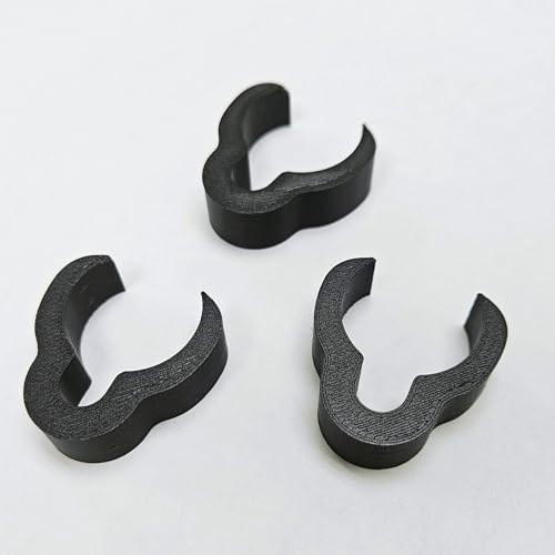
Perfect Fit – Designed to fit 1 1/8” and 1 1/4” transducer poles Secure Hold – Clips snap firmly in place and will not slip off freely 3 Pack Value – Includes three clips for complete cable organization Cable Protection – Prevents tangles and keeps cables safe from snags Made for Anglers – Streamlined design tested for real fishing conditions

【Durable and Waterproof Material】This trolling motor cable sleeve is crafted from thick, flexible, and waterproof neoprene material, ensuring long-lasting durability even in harsh marine environments.The classic black design seamlessly matches any boat decoration style, making it both functional and aesthetically pleasing for protecting your troll motor cable sleeve from seawater, rain, wind, and sun exposure.

Protects & Organizes Cables: Helps secure fish finder and transducer wires along the trolling motor shaft to reduce tangling, rubbing, and cable movement during operation
Check Cable Slack and Transducer Alignment Before Tightening
Checking cable slack and transducer alignment before tightening is essential to ensure optimal performance and prevent damage. Leave enough slack in the cables so they can move freely as the motor transitions from stow to deploy. This prevents wires from stretching or connectors from pulling, which could cause wear or failure over time. The slack also acts as strain relief, reducing the risk of damage from motor movement. When selecting a camera for this setup, choose one with high-definition video to match the clarity of modern sonar displays. For a clean installation, consider using durable marine labels for switch panels to identify the new transducer controls. When selecting the audio components for your boat, look for marine speakers with LED lights to enhance nighttime visibility and ambiance.
Alignment is equally important for mounting stability and accurate readings. Position the transducer face parallel to the motor’s bottom and pointing away from the propeller. Keep the clamp or knob loose enough to make adjustments until the transducer is straight and centered. Once the cable runs freely and the transducer is aligned properly, tighten the hardware securely, but avoid overtightening. Recheck for any binding, twisting, or misalignment to ensure everything remains properly positioned.

🛥️[Product Overview] Stern Pad, Screwless Transducer Mounting Plate kit, Marine-Grade Transducer Mounting Board Hardware Kit.

【Enjoy Fishing Life Better】 Frustrated because the picture on your electronics wasn’t the same as advertised? 7400931 MHX XNT Transducer Bracket is a nice addition for your boat that helps your skimmer transom mount transducer to find fish easier to find and get the right scan image. Efficiently improve your transducer running performance without letting go of any fish!
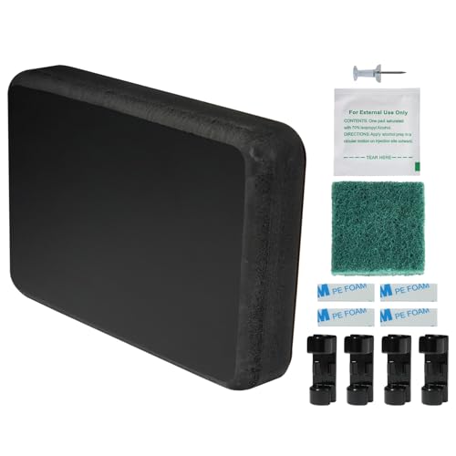
🛥️[Product Overview] Stern Pad, Screwless Transducer Mounting Plate kit, Marine-Grade Transducer Mounting Board Hardware Kit.
Test Stow, Deploy, and Run: Function Check on the Water
To verify your transducer functions correctly, start by fully deploying and then stowing the trolling motor multiple times. Ensure the cable moves smoothly without binding or pinching throughout its entire travel range, as the air hose acts as a flexible protective conduit to prevent damage during this movement. Next, power on your chartplotter and select a 2D sonar view. Make sure the water depth is at least 2 feet to get an accurate reading. A clear bottom return with a digital depth readout indicates the transducer is properly submerged and operational. To help ensure this reading remains stable, the housing should be built for waterproof durability against constant water exposure. Always confirm that the horn relay connection is secure to avoid any electrical interference with the sonar signal. For enhanced navigation and safety, consider pairing your setup with a top marine radio with AIS for better sailing coordination.
Test the signal quality at slow speeds, then gradually increase your boat’s pace. Watch for any degradation in the bottom return; if the sonar signal drops out at higher speeds, note the specific speed where this occurs. Perform moderate turns and observe if the sonar image improves. If it does, you might need to fine-tune the transducer’s position. If not, consider relocating the mount to achieve a better signal and consistent readings.
Set the Transducer Parallel to the Bottom for Accurate Sonar
To ensure accurate sonar readings, set the transducer so that it remains parallel to the bottom. Mount the bracket with the narrow end facing away from the propeller. Then, position the transducer against the motor housing and check that its face is level with the waterline before tightening any bolts. Avoid relying on the stowed position, as it may differ from the actual operating angle. Secure the mount using clamps or ties, but do not overtighten, as this can prevent proper alignment. Route the cable without tension along the shaft to avoid snags and shifting. Finally, route the cable carefully without tension, since pulling can shift the transducer out of parallel. Confirm that the transducer remains aligned with the waterline one last time before fully tightening everything. For optimal setup, consider that marine radio offers clearer communication than CB radio for boating needs. Unlike a thru-hull transducer mounted through the hull, this trolling motor install requires careful surface alignment.
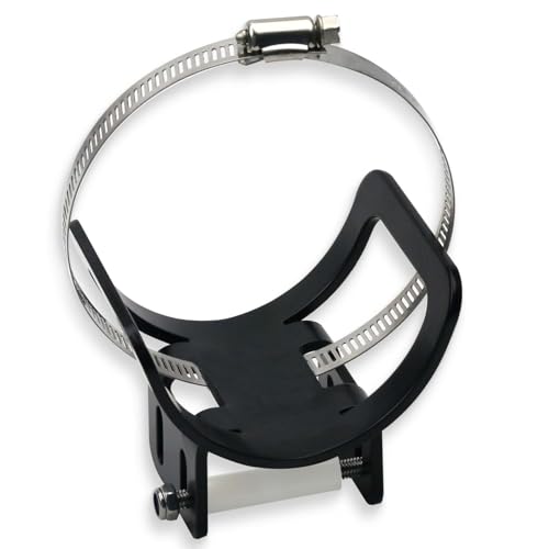
Precision Fitment: Designed as direct replacement for part numbers 410150-1, 1840201, and MKR-15 – mounts transducer to lower unit of Minn Kota bow-mount and transom-mount trolling motors with shaft diameters of 3-1/4", 3-5/8", 4", and 4-1/2"

Mount Transducer to Trolling Motor: Adapter bracket converts a MEGA Side Imaging+ transom-mount transducer for trolling motor use

Great Compatibility - Universal trolling motor mount for clamp-on electric trolling motors, fits electric trolling motors only. Not suitable for outboard engines of any size. Universal fit for any boat with a flat spot on the stern big enough for a power pole.
Three Common Transducer Alignment Errors That Skew Readings
Tilt or roll misalignment, typically around 5 degrees or more, causes depth readings to become inconsistent. When the transducer is rolled, it shifts the sonar beam off directly beneath the boat, making suspended targets appear higher or lower than their actual position. To fix this, check the angle control settings or use shims to ensure the transducer is level. Proper sonar calibration depends on accurate alignment, so taking the time to get this right will improve the reliability of your depth data. Checking alignment by moving the trolling motor head up and down to observe gap changes is a visual adjustment technique that ensures the beam points directly with the motor heading.
Poor placement of the transducer can generate turbulence or interference that distorts readings. Mounting the transducer too high can lead to break water contact, resulting in weak signals. Conversely, positioning it too low may increase drag and noise, obscuring signals. To optimize placement, test your setup by turning the motor off—if your returns improve, adjust the transducer’s position to find the cleanest, most consistent data stream.

Complete Kit for Easy Installation: Our no drill transducer mount kit includes all necessary accessories for a seamless installation: 1 transducer pad block, 1 scouring pad, 1 cleaning wipe, and 3 black cable clips; Simply clean the installation surface, peel off the adhesive, align the position, and press firmly for a few minutes; (Note: Please wait 18 hours before mounting the transducer to ensure the adhesive sets firmly, reducing the risk of detachment during use

🛥️[Product Overview] Stern Pad, Screwless Transducer Mounting Plate kit, Marine-Grade Transducer Mounting Board Hardware Kit.

Please see the "Stern Pad Strength Demo Video" on You-tube